Gas Spring Force Calculator
Calculate the required force for your gas springs based on dimensions and weight
Diagram
How to Use This Calculator
- Enter the total weight your application needs to support
- Input the dimensions of your setup (A, B, and gas spring position)
- Specify the angle at which you want to calculate the force
- Enter the number of gas springs you plan to use
- Click “Calculate Force” to get your results
Gas Spring Installation Tips
- Always mount gas springs with the rod facing downward
- Allow at least 10mm clearance at both ends for movement
- Consider environmental factors (temperature affects pressure)
- For safety, choose springs with 20% more force than calculated
- Consult a professional for critical applications
Calculation Formula
The gas spring force is calculated using the following formula:
Where:
- F = Required gas spring force (N)
- W = Weight to support (kg)
- g = Gravitational acceleration (9.81 m/s²)
- B = Length from pivot to load (m)
- θ = Opening angle (degrees)
- A = Length from pivot to gas spring (m)
- n = Number of gas springs

How it works:
- Sealed System:A gas spring is a closed system containing a gas, typically nitrogen, and oil.
- Piston Movement:As the piston moves within the cylinder, it compresses the gas, increasing the pressure.
- Force Generation:The increased pressure against the piston creates a force that opposes the piston’s movement.
- Boyle’s Law:The relationship between pressure and volume is governed by Boyle’s Law, which states that at a constant temperature, the volume of a gas is inversely proportional to its pressure.
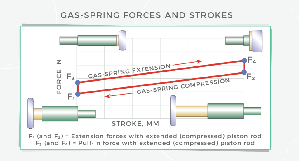
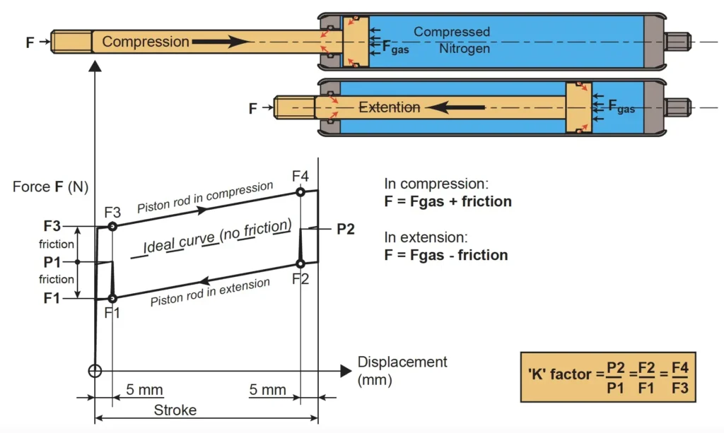
- K-Factor:The change in force as the piston moves from its fully extended to fully compressed position is known as the K-factor (or gas spring progression).
- P1 Force:The force at the fully extended position is called the P1 force.
- P2 Force:The force at the fully compressed position is called the P2 force.
- Force Calculation:The force of a gas spring can be calculated using the formula: Force = Pressure x Area.
- Factors Influencing Force:The force is influenced by several factors, including the stroke (length of movement), cylinder and piston rod diameter, the amount of oil, and the temperature.
Key Considerations:
- Temperature: Gas spring force is affected by temperature. A temperature increase can cause a slight increase in force, and a temperature decrease can cause a decrease.
- Friction: Friction between the piston and cylinder can affect the force output.
- Progression (K-Factor): The difference between the P1 and P2 forces, indicating how the force changes during the stroke.
Gas spring force formula
The force exerted by a gas spring is calculated by multiplying the pressure inside the spring by the area of the piston. The formula for gas spring force is: F = P * A, where F is the force, P is the pressure, and A is the area. The units for force would be Newtons (N), pressure would be in Pascals (Pa), and area would be in square meters (m^2).
Elaboration:
- Piston Area:The piston area is the surface area of the piston that is in contact with the gas.
- Pressure:The pressure inside the gas spring is determined by the gas’s properties (like temperature and volume) and the sealed volume of the spring.
- Force:The force is the resulting force that the gas spring can exert, typically measured in Newtons (N).
- Static Force (P1):In the extending direction, the force output of a gas spring is defined as its P1 force, which is the static force measurement taken 5mm from full extension.
Gas spring force chart

A gas spring force chart typically illustrates the relationship between the force output (often in Newtons or pounds) and the diameter or size of the gas spring. These charts help engineers and users select the appropriate gas spring for a specific application based on the required force. Generally, larger diameters correspond to higher forces, as the larger piston area experiences more pressure.
Here’s a more detailed look at what you can expect to see in a gas spring force chart:
1. Force vs. Diameter/Size:
- Charts often show a direct relationship between the diameter (or size designation, like M5, M8, etc.) and the force output the gas spring can produce.
- For example, Gasspringsshop lists gas spring sizes (4-12, 6-15, etc.) and their maximum force capabilities (e.g., up to 200N, 450N, respectively).
- Other charts might show force ranges within different sizes, indicating that the specific force output can vary depending on other factors like internal pressure.
2. Key Considerations:
- Piston Rod Diameter:The larger the piston rod diameter, the larger the piston area, and thus the greater the force generated for a given internal pressure.
- Internal Pressure (Charging Pressure):The pressure of the gas inside the spring significantly impacts the force output. Higher pressure generally leads to higher forces, but this also depends on the spring’s design and materials.
- K-Factor:The K-factor refers to the increase in force as the piston rod is compressed. This is important to consider if the application requires the spring to generate different forces in different positions.
- Friction:Friction within the gas spring can reduce the actual force output compared to the theoretical force.
- Force Ratio (P2/P1):This ratio indicates how much the force changes during the spring’s stroke. Standard gas springs typically have force ratios between 1.2 and 1.4.
3. Examples of Force Charts:
- Lesjöfors Group provides force tolerance charts that show the allowed deviations in force output for different force ranges (e.g., +/- 10 N for forces less than 100 N).
- Dadco offers charts that relate force output to pressure for different models of nitrogen gas springs, along with conversion factors for different units of measurement.
- Camloc provides diagrams illustrating typical force ratios for various gas spring sizes.
By understanding these factors and consulting force charts, users can select gas springs that are appropriate for their specific needs and ensure they are operating within the expected force ranges.
